Pipelining and Parallelism
Quantify pipeline speedup, resolve instruction hazards, and compare scalar, superscalar, vector, attached-array, and SIMD organizations.
Updated
Learning objectives
- Classify parallel organizations with Flynn's taxonomy
- Construct pipeline timing diagrams and calculate throughput and speedup
- Explain arithmetic and instruction pipeline stages
- Identify structural, data, and control hazards and their remedies
- Explain RISC, superscalar, vector, interleaved-memory, and array processing
Prerequisites
- Instruction Set Design
- Computer Arithmetic
- Memory Hierarchy
Parallel processing performs multiple useful operations during the same interval. It may duplicate functional units, divide work into pipeline stages, apply one instruction to a vector, or coordinate many independent processors.
| Term | Definition |
|---|---|
| Latency | Time from starting one task until its result is complete. |
| Throughput | Number of completed tasks per unit time after the system is active. |
| Stage | Combinational suboperation bounded by pipeline registers. |
| Hazard | A condition that prevents the next instruction from advancing normally. |
| Stall | A cycle in which selected pipeline state is deliberately held. |
| Bubble | An empty pipeline slot that moves through later stages. |
A pipeline improves throughput before it improves latency. A four-stage pipeline may still take four cycles to produce one result; its advantage is completing later results one cycle apart.
Forms of Parallel Processing
Flynn classifies machines by the number of simultaneous instruction and data streams.
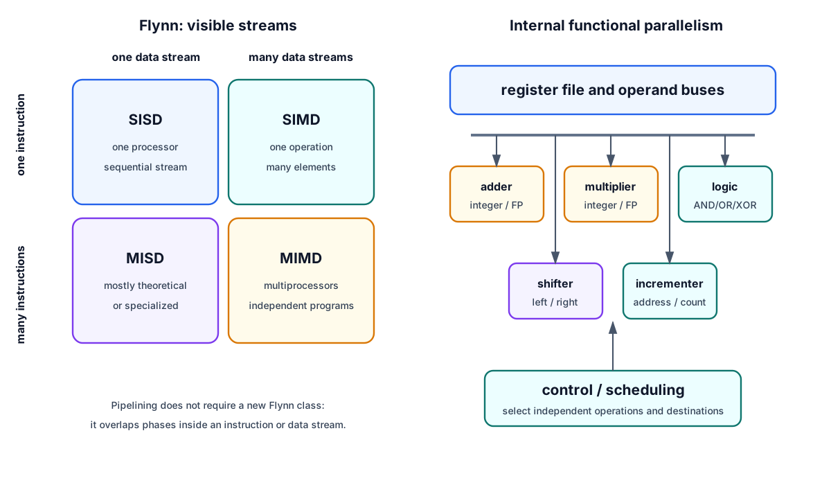
| Class | Instruction streams | Data streams | Typical interpretation |
|---|---|---|---|
| SISD | 1 | 1 | Conventional sequential processor; may have internal pipelines |
| SIMD | 1 | Many | Array processor or vector-style lanes executing one operation |
| MISD | Many | 1 | Mainly theoretical/specialized fault-tolerant flows |
| MIMD | Many | Many | Multiprocessors and multicomputers running several programs |
Independent adders, multipliers, logic units, and shifters can operate simultaneously on different values. This improves throughput but requires a controller to allocate operands and prevent resource conflicts. Large-scale applications include weather forecasting, aerodynamics, finite-element analysis, remote sensing, medical imaging, genetics, AI, and scientific simulation.
Pipeline Principle
A pipeline decomposes one operation into suboperations. Each stage has combinational logic followed by a register; a common clock advances every intermediate result. After filling, different stages work on different tasks and ideally complete one task per cycle.
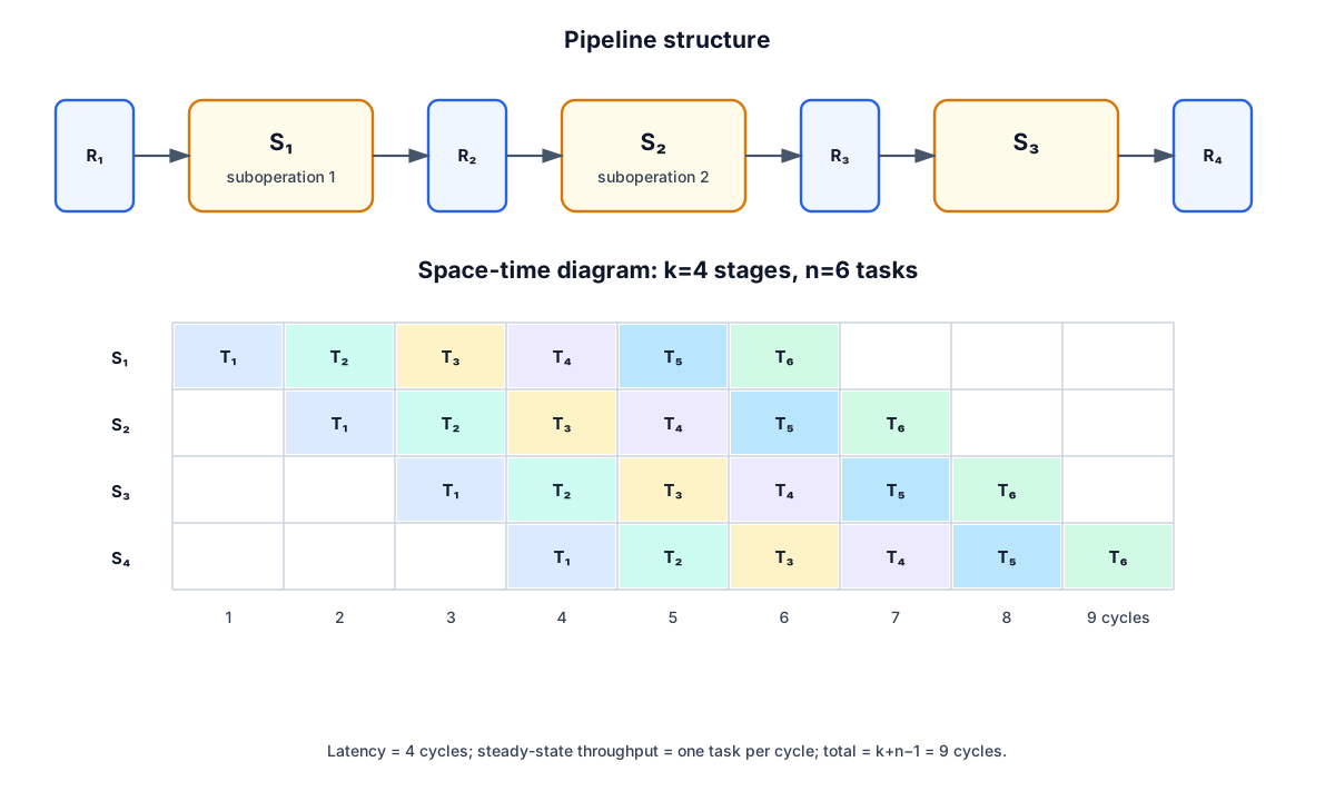
For tasks, stages, and pipeline clock period :
If a nonpipelined unit takes per task:
If balanced stages divide the same work so , then as grows, . Real speedup is lower because the slowest stage fixes the clock, pipeline registers add delay, and stalls create empty slots.
Numeric example
A four-stage pipeline with ns executes 100 tasks in
The equivalent 80 ns nonpipeline unit needs ns, so
The result approaches the theoretical fourfold limit for a long stream. If the nonpipeline operation were only 60 ns, the asymptotic speedup would be .
A Three-Stage Data Pipeline
Compute with:
- Load .
- Multiply and delay .
- Add the product to the delayed .
For seven input triples, the first result appears at clock 3 and the last at clock 9:
| Clock | Stage 1 registers | Stage 2 registers | Stage 3 output |
|---|---|---|---|
| 1 | — | — | |
| 2 | — | ||
| 3 | |||
| 4 | |||
| 9 | — | — |
The delay register for is essential: it keeps each addend aligned with its matching product.
Arithmetic Pipelines
Floating-point addition/subtraction naturally separates into:
- Compare exponents.
- Align the smaller significand by shifting.
- Add or subtract significands.
- Normalize the result and adjust its exponent.
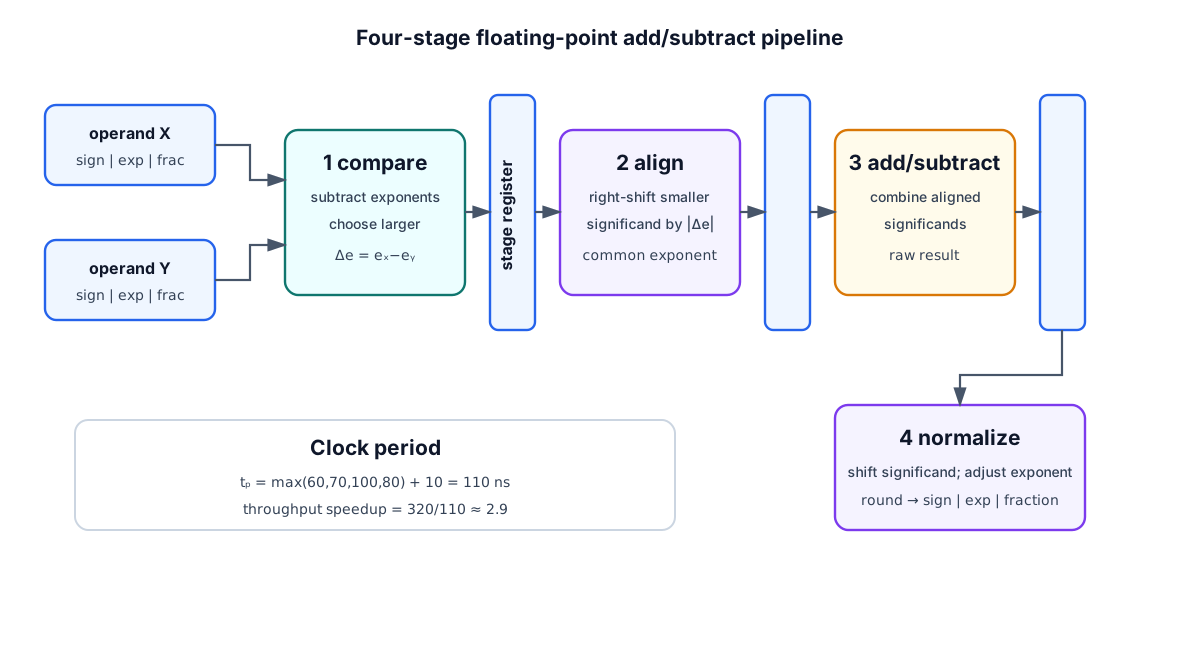
If combinational stage delays are 60, 70, 100, and 80 ns and each interstage register adds 10 ns, the clock must be ns. The equivalent unpipelined path is ns, giving an asymptotic throughput speedup , not four, because the stages are unbalanced.
Fixed-point multiply and divide can also be pipelined by unrolling their repeated add/subtract and shift steps into separate stages.
Instruction Pipelines
An instruction pipeline overlaps phases of successive instructions. A general six-phase breakdown is fetch instruction, decode, calculate effective address, fetch operand, execute, and store result. Combining decode with address calculation and execute with write-back yields the source’s four stages:
FI: fetch instruction.DA: decode and calculate effective address.FO: fetch operand.EX: execute and store result.
In cycle 4, instruction 1 can be in EX, instruction 2 in FO, instruction 3 in DA, and instruction 4 in FI. Separate instruction and data memories or caches allow FI and FO to access memory simultaneously.

Pipeline hazards
| Hazard | Cause | Example | Remedies |
|---|---|---|---|
| Structural | Two stages need one resource | FI and FO share one memory port | Duplicate/partition resource or stall |
| Data | Operand is not ready | ADD R1,... followed by SUB ...,R1 | Forward/bypass, interlock stall, compiler scheduling |
| Control | Next PC is unknown | Conditional branch or interrupt | Predict, prefetch target, delayed branch, flush |
Forwarding routes a computed result directly to a later ALU input before it reaches the register file. A hardware interlock inserts a bubble when forwarding cannot satisfy the timing, as with some load-use pairs. A compiler may reorder independent instructions or insert a no-operation; this is delayed load.
Branch handling
- Prefetch both paths: fetch sequential and target instructions until the decision.
- Branch target buffer (BTB): associative memory remembers branch PCs, targets, and sometimes target instructions.
- Loop buffer: holds a small repeated instruction sequence close to fetch.
- Branch prediction: guess direction/target and discard speculative instructions if wrong.
- Delayed branch: define one or more instructions after the branch to execute regardless; the compiler fills these delay slots with useful work when possible.
An interrupt also changes the PC. The pipeline completes or discards in-flight work according to the machine’s precise-interrupt rules before fetching from the handler.
RISC and Superscalar Pipelines
RISC instructions are usually fixed length, have simple addressing, use a load/store organization, and perform register operations in uniform stages. These properties make stage timing and decode regular. A classic three-segment teaching pipeline is I fetch, A ALU/address operation, and E memory/write result.
A load can still create a delayed-load hazard because its value becomes available late. A delayed branch exposes the branch slot to software. Modern processors normally maintain the architectural illusion with interlocks and prediction, but compiler scheduling remains useful.
A superscalar processor issues more than one scalar instruction per cycle using multiple pipelines/functional units. Unlike one vector instruction, each issued instruction still names its own scalar operation and operands. Dependencies, available units, and commit order limit issue width.
Vector Processing
A scalar loop
for i = 1..100:
    C[i] = A[i] + B[i]
fetches and decodes loop-control instructions repeatedly. A vector processor expresses the work as one operation:
A vector instruction includes an operation, source and destination base addresses or vector registers, and vector length. A pipelined functional unit accepts successive element pairs; after startup, it can produce one result per cycle.
Matrix multiplication and inner products
For ,
An product contains inner products and multiply-accumulate terms. A product therefore performs 27 multiply-accumulates when each starts at zero. Linked multiplier and adder pipelines stream the pairs and accumulate partial sums.
Interleaved Memory
Vector and instruction pipelines demand several words close together. In an -module interleaved memory, low address bits choose the module and the remaining bits choose a word within it:
For four modules, addresses 0,1,2,3 go to modules 0,1,2,3; addresses 4,5,6,7 repeat the pattern. Each module has its own address/data registers, so staggered requests overlap. Sequential words can approach one word per bus cycle even when one module’s internal cycle is longer.
Array Processors
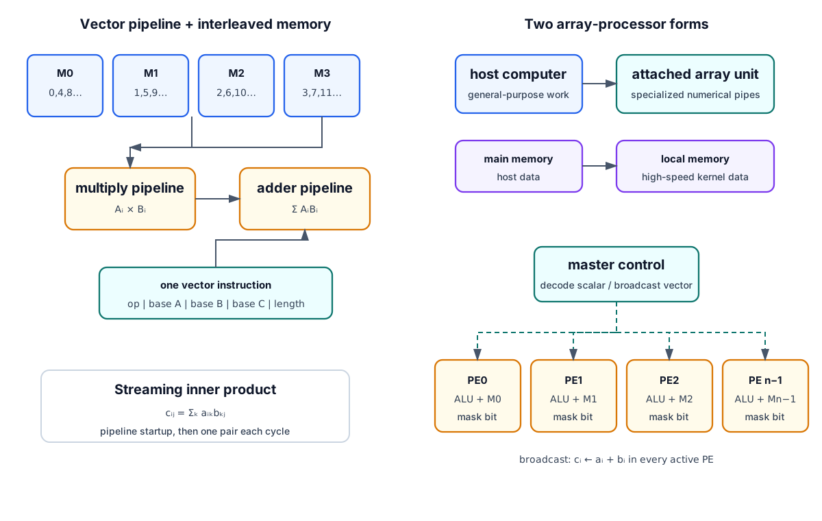
An attached array processor is an auxiliary numerical processor connected to a conventional host through an I/O interface and a high-speed main-to-local-memory path. The host handles general work; the attached unit provides pipelined floating-point adders and multipliers for scientific kernels.
An SIMD array processor contains many identical processing elements (PEs), each with an ALU, registers, and local memory, governed by one master control unit. Scalar/control instructions execute at the master; vector instructions broadcast to active PEs. For , PE stores and all active PEs compute simultaneously. Masks disable PEs outside the current vector portion; a vector longer than the PE count is processed in batches.
| Organization | Instruction overhead | Parallel resource | Strong workload |
|---|---|---|---|
| Scalar pipeline | One scalar instruction at a time | Overlapped stages | General instruction streams |
| Superscalar | Several scalar instructions/cycle | Multiple issue units | Independent instruction-level work |
| Vector processor | One instruction for many elements | Pipelined vector units | Long regular vectors/matrices |
| SIMD array | One broadcast instruction | Many PEs | Highly data-parallel arrays |
| Attached array processor | Host dispatch plus kernel | Specialized back-end | Accelerated numerical routines |
Check Your Understanding
- How many cycles do eight tasks need in a five-stage ideal pipeline?
- Why does the slowest stage determine the pipeline clock?
- Classify a 64-PE array executing one add on 64 different pairs.
- How many multiply-accumulates form a matrix product?
- Which hazard is removed by separate instruction and data memories?
Answers
- cycles.
- Every stage must finish before the common register edge.
- SIMD.
- .
- The structural conflict between instruction fetch and operand access.