Instruction Set Design
Encode operations and operands, compare zero- through three-address formats, calculate expanding opcodes and Huffman codes, resolve addressing modes, and trace program control.
Updated
Learning objectives
- Separate opcode, addressing-mode, register, and memory-address fields
- Compare block, expanding-opcode, and Huffman encoding
- Calculate encoding capacity for mixed address formats
- Compute effective addresses for major addressing modes
- Explain data transfer, arithmetic, logic, system, branch, subroutine, and interrupt instructions
- Relate condition flags to conditional program control
Prerequisites
- Computer Organization
- Datapath and Microoperations
An instruction tells the processor what operation to perform and where its operands come from. A sequence of instructions forms a program. The instruction-set architecture (ISA) defines the binary contract between software and the processor.
| Term | Definition |
|---|---|
| Opcode | The bits that identify the operation, such as add, load, or branch. |
| Operand | A value consumed by the operation; it may be explicit or implied. |
| Address field | Bits that help identify an operand location, not necessarily the final memory address. |
| Addressing mode | The rule that interprets operand fields and forms the effective address. |
| Effective address (EA) | The memory address obtained after applying the addressing-mode calculation. |
Do not equate an opcode with an instruction. The opcode says what operation to perform; the remaining fields say which values participate and how to find them.
Operand-Address Formats
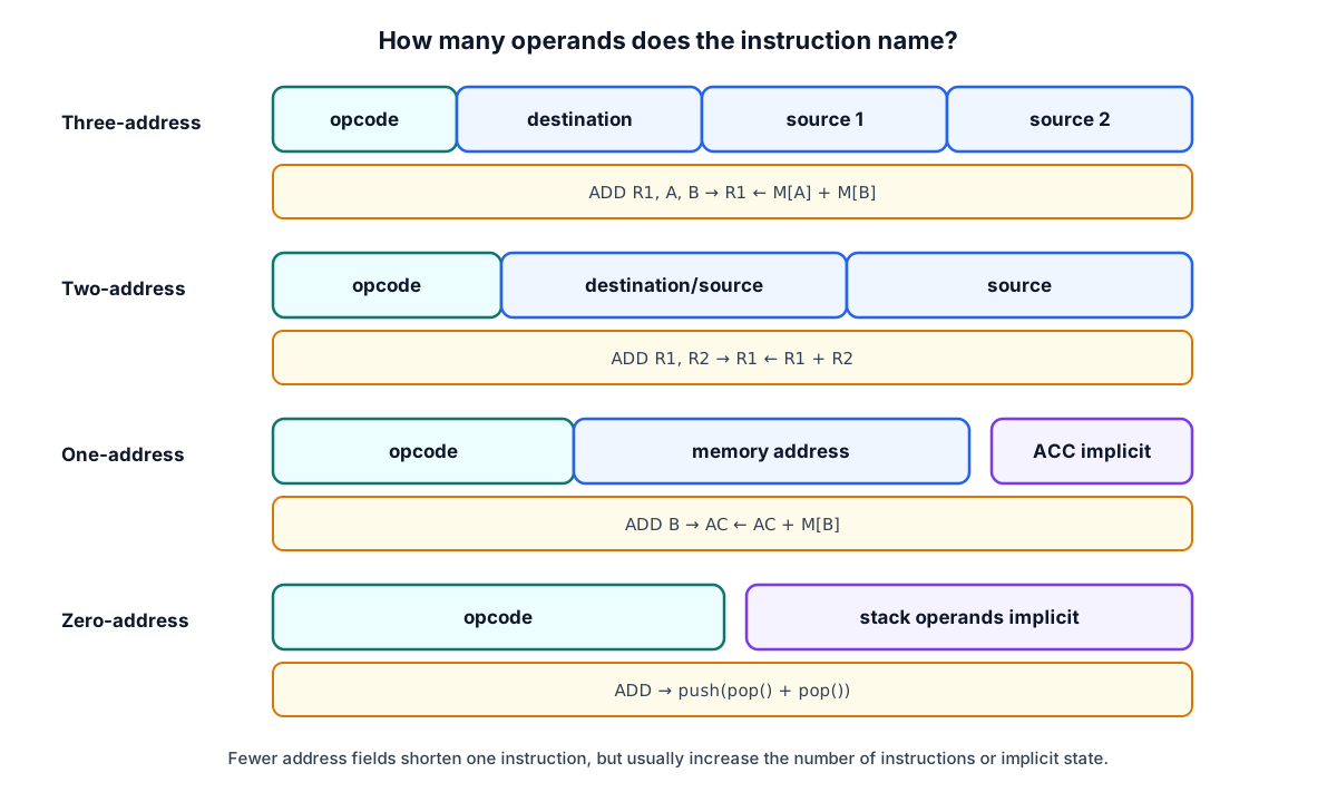
For the expression :
| Format | Representative sequence | Implicit state |
|---|---|---|
| Three-address | ADD R1,A,B; SUB R2,C,D; MUL X,R1,R2 | Destinations are explicit |
| Two-address | MOV R1,A; ADD R1,B; MOV R2,C; SUB R2,D; MUL R1,R2 | First operand is also destination |
| One-address | LOAD A; ADD B; STORE T; LOAD C; SUB D; MUL T; STORE X | Accumulator |
| Zero-address | PUSH A; PUSH B; ADD; PUSH C; PUSH D; SUB; MUL; POP X | Stack top |
Short instructions occupy less memory and can be fetched with fewer bytes. They may also require more instructions, so total program size and execution time depend on the complete encoding rather than one instruction in isolation.
Fixed-Length Block-Code Encoding
A processor can execute an operation only after its opcode has a unique binary pattern. With opcode bits, block coding offers at most patterns. A -to- decoder can activate one instruction line.
| Opcode | Pattern | Opcode | Pattern |
|---|---|---|---|
| LDA | 000 | AND | 011 |
| STA | 001 | CMA | 100 |
| ADD | 010 | INCA | 101 |
| JMP | 110 | HLT | 111 |
Three bits encode exactly eight operations. Adding a ninth operation requires a wider fixed opcode or a different encoding scheme.
Expanding Opcodes
An expanding opcode reuses an otherwise unused short opcode as a prefix for a longer opcode. This trades some operand-field combinations for additional operations with fewer explicit operands.
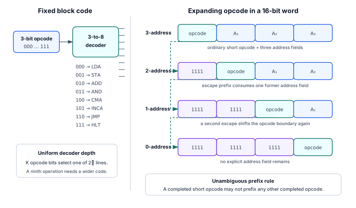
Consider a 16-bit format with a 4-bit opcode followed by three 4-bit addresses. It can encode sixteen three-address operations. If only fifteen are used, prefix 1111 can signal that the next 4-bit field extends the opcode:
ordinary three-address: [ opcode 4 ][ A1 4 ][ A2 4 ][ A3 4 ]
two-address extension:  [ 1111 ][ opcode 4 ][ A1 4 ][ A2 4 ]
one-address extension:  [ 1111 ][ 1111 ][ opcode 4 ][ A1 4 ]
zero-address extension: [ 1111 ][ 1111 ][ 1111 ][ opcode 4 ]
The exact allocation is a design choice. The rule is that decoding must be unambiguous.
Capacity method
Count complete bit patterns rather than merely “unused names.” An -bit instruction space contains encodings. An instruction with address bits consumes complete encodings because its address can vary independently.
Example 1: one- and zero-address instructions
A byte-addressable 64 B memory needs 6 address bits. With a 4-bit opcode, there are 16 short opcode patterns. Ten are used for one-address instructions, leaving six prefixes. Each prefix can absorb all former address patterns:
zero-address instructions.
Example 2: three- to two-address expansion
A 22-bit instruction has one 4-bit register field, two 6-bit memory-address fields, and therefore a 6-bit three-address opcode. Of 64 possible opcodes, 62 are used. Each of the two remaining prefixes can extend through one 6-bit field:
two-address operations.
Example 3: mixed 58 and 25 operations
A processor needs 58 three-address operations and 25 two-address operations; each address selects one of 16 locations.
- Address width: bits.
- Three-address opcode width: bits.
- Fixed instruction length: bits.
- Unused 6-bit prefixes: .
- Two-address capacity: , enough for 25 operations.
- Two-address opcode width: bits.
Example 4: count the complete 11-bit space
An 11-bit format has 4-bit address fields, five two-address instructions, and 32 one-address instructions:
zero-address encodings remain.
Huffman Opcode Encoding
If opcode frequencies are known, a prefix-free Huffman code minimizes the weighted average code length:
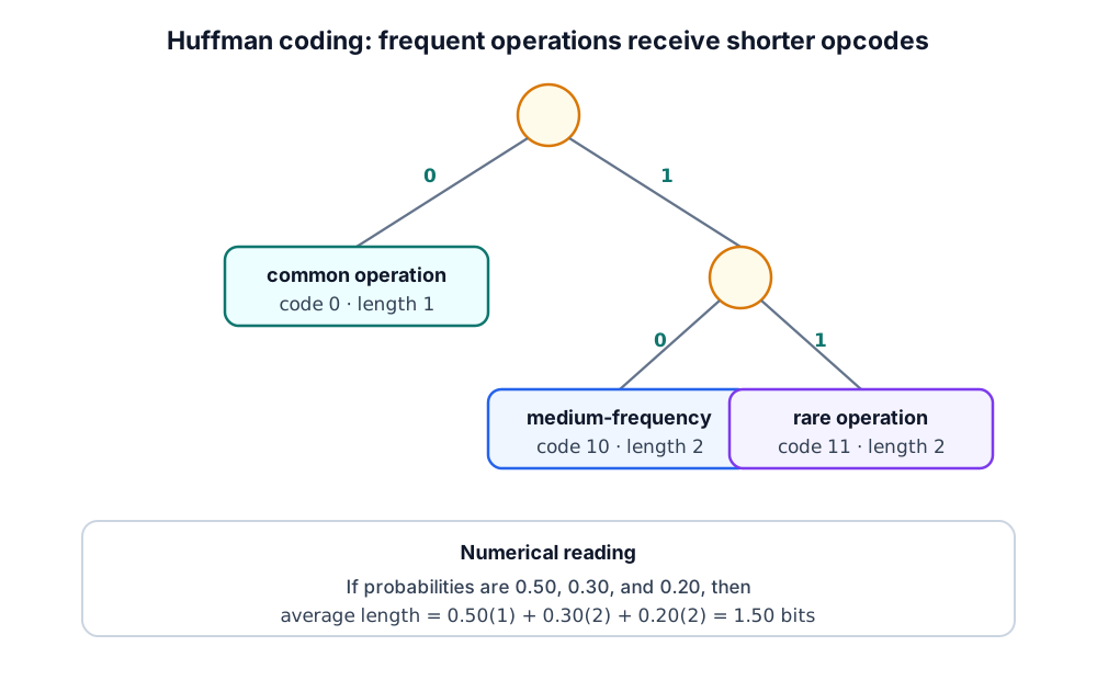
- Create one leaf for each operation and label it with its probability.
- Repeatedly combine the two smallest unmarked probabilities.
- Label the two branches
0and1. - Read each code from root to leaf.
Frequent instructions get short codes; rare instructions get long codes. The source example assigns codes of lengths 2–4 to operations such as LOAD, STORE, SHIFT, NOT, JUMP, HALT, AND, and ADD.
For the characters in Mississippi, frequencies are , , , and . One valid Huffman tree gives lengths 3, 3, 2, and 1:
The advantage is minimum expected bits. The disadvantages are variable boundaries, serial prefix recognition, and a more complex decoder. Practical instruction sets usually favor regular parallel decoding even when a pure Huffman code is denser.
Addressing Modes
An addressing mode defines how an instruction obtains an operand or its effective address ().
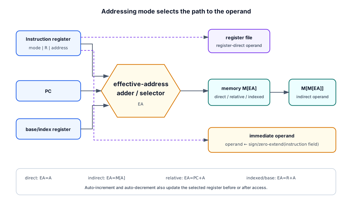
Assume the instruction contains value/address , register , word size , and :
| Mode | Operand or effective address | Example meaning |
|---|---|---|
| Inherent | Operand implied by opcode | CLI clears the interrupt-enable flag |
| Immediate | Operand | ADD #250,R1 |
| Direct/absolute | Operand | |
| Register | Operand | No data-memory access |
| Register indirect | Operand | |
| Auto-increment | , then | Traverse forward through words |
| Auto-decrement | , then | Stack push or reverse traversal |
| Indexed | Large index plus address/offset | |
| Base plus displacement | Structure field or stack-frame item | |
| PC-relative | Position-independent branch | |
| Memory indirect | Address field points to a pointer |
The terms indexed and base-relative can use identical addition hardware. Their distinction is the programming interpretation and typical field width. Auto-indexing means the register is modified as part of operand access.
Instruction Classes
Data transfer
MOV, LOAD, STORE, stack push/pop, and register exchange move values without changing their bit patterns. The datapath still needs source selection, a route, and a destination write enable.
Arithmetic and logic
ADD, SUB, MUL, DIV, AND, OR, NOT, shifts, and rotates select ALU or iterative arithmetic functions. These instructions usually update condition flags.
System control and I/O
System instructions change privileged state, interrupt masks, or processor modes. Separate-I/O architectures use explicit input/output instructions; memory-mapped I/O uses ordinary load/store operations to special addresses.
Program control
- unconditional branch:
BR NEXT; - conditional branch: test a flag and possibly replace ;
- counted branch: decrement a register and branch until a condition;
- subroutine call: save a return address and branch;
- return: restore the saved address;
- trap: request a synchronous software interrupt.
Status Register and Conditional Control
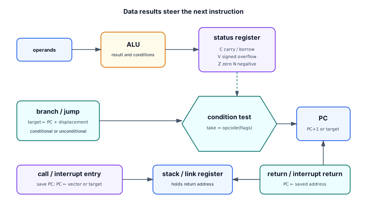
| Flag | Typical setting condition | Unsigned/signed use |
|---|---|---|
| Result is all zeros | Equality and loop termination | |
| or | Result sign bit is 1 | Signed negative |
| Carry out / no borrow under the chosen convention | Unsigned overflow and multiword arithmetic | |
| Signed result is outside representable range | Signed overflow | |
| Interrupts globally enabled | Controls asynchronous service acceptance |
For four-bit addition 1111 + 0001 = 1 0000, , , , and : unsigned 15 overflowed to zero, while signed is valid.
An external interrupt resembles a hardware-generated subroutine call but may arrive asynchronously. The processor finishes or safely suspends current work, saves and required status/register state, loads an interrupt-vector address, runs the service routine, then restores state before returning.
Instruction Execution at Register-Transfer Level
The foundation cycle becomes concrete when fields and addressing modes are included:
| Phase | Representative microoperations |
|---|---|
| Fetch address | |
| Fetch word | |
| Capture/decode | ; decode opcode and mode |
| Effective address | if required |
| Operand read | or select source register/immediate |
| Execute | ; compute flags |
| Write-back | destination |
| Interrupt check | if enabled request pending, save state and load vector |
Not every instruction uses every phase. A register-register ADD needs no data-memory operand access; a STORE has no ALU result write-back; a taken branch writes .
Self-Check
- Why is a zero-address instruction not an instruction with no operands?
- A fixed opcode has 37 operations. What minimum opcode width is required?
- With and displacement , what is the base-relative effective address?
- Why can and for the same addition?
Answers
- Its operands are implicit, usually at the top of a stack.
- bits.
- .
- Carry reports the unsigned boundary; overflow reports the signed boundary.