Input Output Systems
Connect asynchronous peripherals through interfaces, compare programmed and interrupt-driven transfer, arbitrate priority, and trace DMA and IOP operation.
Updated
Learning objectives
- Explain the registers and control logic in an I/O interface
- Compare strobe and handshaking transfers
- Distinguish programmed I/O, interrupts, DMA, and I/O processors
- Explain software, daisy-chain, and parallel interrupt priority
- Initialize a DMA controller and trace bus request through completion
Prerequisites
- Instruction Set Design
- Control Unit Design
- Memory Hierarchy
Peripherals differ from the CPU in speed, data format, electrical signaling, and timing. An I/O interface absorbs those differences so the processor sees regular data, status, and control registers rather than device-specific signals.
| Term | Definition |
|---|---|
| Peripheral | An external input, output, or storage device controlled by the computer. |
| Interface | Registers and logic translating between the system bus and a device protocol. |
| Transducer | A component converting a physical quantity to or from an electrical/binary signal. |
| Polling | Repeated CPU tests of a status bit until a device becomes ready. |
| Interrupt | A request that diverts the CPU to a service routine at a defined boundary. |
| Bus master | The unit currently permitted to drive bus address and control signals. |
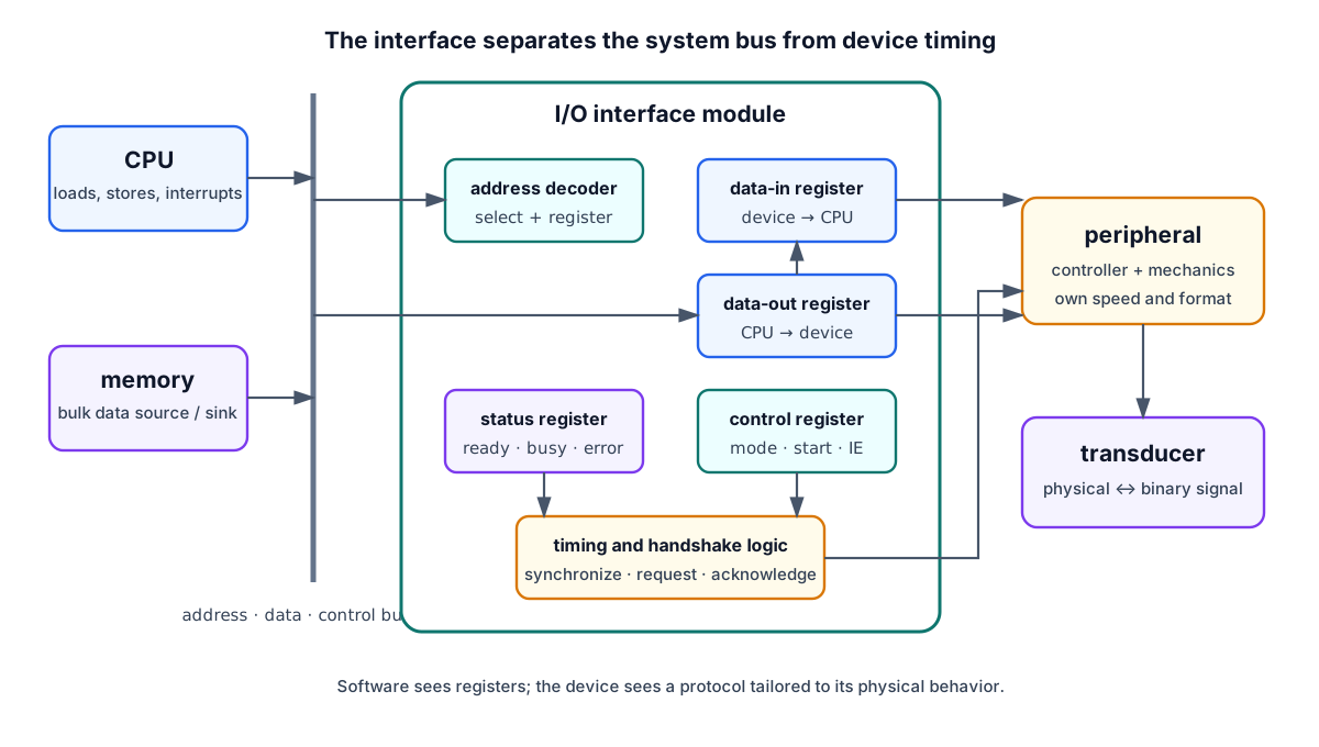
Interface Module
| Register/logic | Purpose |
|---|---|
| Data-in register | Holds a word received from the peripheral |
| Data-out register | Holds a word to be sent to the peripheral |
| Status register | Ready, busy, error, interrupt-pending flags |
| Control register | Direction, start, mode, interrupt enable |
| Address decoder | Selects this interface and one of its registers |
| Timing/handshake logic | Coordinates device and bus events |
The device side may include a transducer: a keyboard converts motion to a code; a display converts bits to light. The system side uses the address, data, and control buses.
With memory-mapped I/O, interface registers occupy normal address space and ordinary loads/stores access them. With isolated I/O, a separate address space and special I/O instructions distinguish device transfers.
Asynchronous Data Transfer
The CPU bus and a peripheral usually do not share one clock. A transfer needs a timing convention.
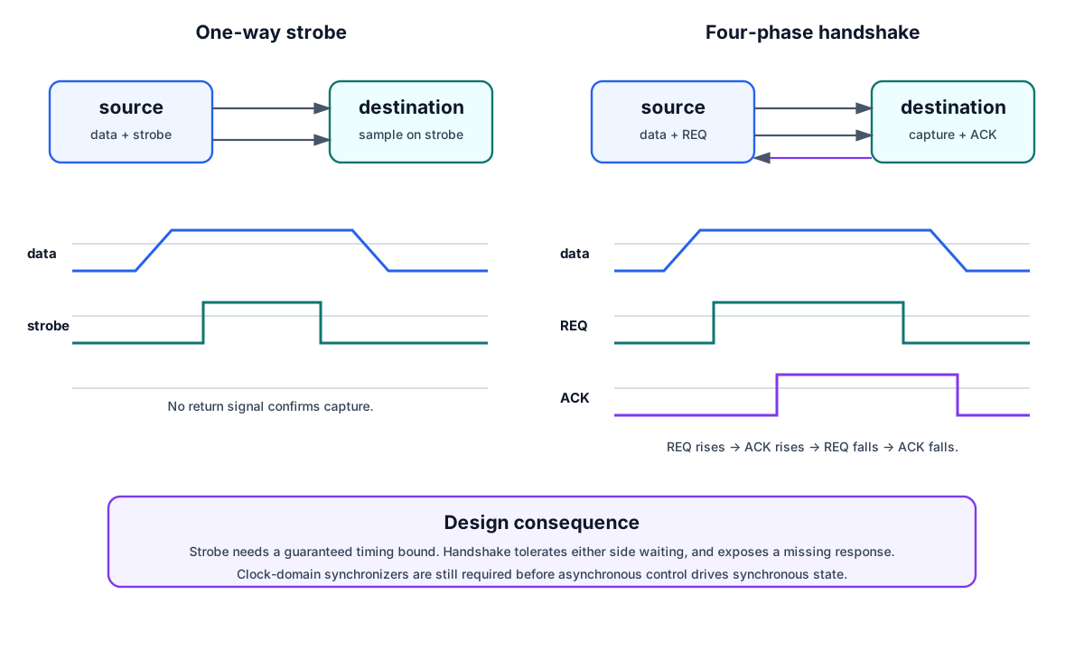
Strobe control
- Source-initiated: source places data, asserts strobe, then removes strobe and data after the specified interval.
- Destination-initiated: destination asserts strobe/request; source responds by placing data.
The single control line assumes a bounded response time. If a device is missing or too slow, no acknowledgement reports the failure.
Handshaking
For source-initiated transfer:
- Source places data and asserts
REQ/data-valid. - Destination captures data and asserts
ACK. - Source removes
REQand data. - Destination removes
ACK; the channel is ready again.
This four-phase protocol tolerates arbitrary relative speeds. A destination-initiated version begins with a ready/request from the receiver. Synchronizers are still needed where an asynchronous control enters clocked logic.
Modes of I/O Transfer
Memory is ultimately the source or destination of bulk information; the processor transforms it. The question is how much CPU involvement moves each word.
| Mode | Who tests readiness? | Who moves each word? | CPU cost | Best use |
|---|---|---|---|---|
| Programmed I/O | CPU polling loop | CPU instruction | Highest | Simple/rare transfers |
| Interrupt-driven I/O | Device interrupts CPU | CPU service routine | Per-event overhead | Irregular moderate-rate devices |
| DMA | DMA controller | Hardware between device and memory | Setup + completion | Blocks and fast devices |
| I/O processor | IOP program | IOP/DMA paths | Command-level | Complex concurrent I/O |
Programmed input resembles:
while READY == 0:        // busy wait
    continue
R1 ← DATA_IN
READY ← 0
It is simple, but the CPU repeatedly reads status. Interrupt-driven I/O lets useful computation continue and requests service only when needed.
For scale, moving a 1 MiB block as 4-byte words requires transfers. If a polling loop and move consume eight instructions per word, the CPU executes about million instructions just to copy the block. DMA replaces that per-word work with setup and completion handling; the bus still transfers every byte, but the CPU is free between those two events.
Interrupt Sequence and Priority
At an accepted interrupt, the processor completes a defined boundary, saves a return address and necessary state, identifies the source, disables or masks unsafe nesting, and loads the handler address. The interrupt service routine (ISR) services the device and restores the interrupted context.
Priority determines which simultaneous request is serviced first and which sources may preempt a current handler. High-rate devices such as storage normally outrank slow human-input devices.
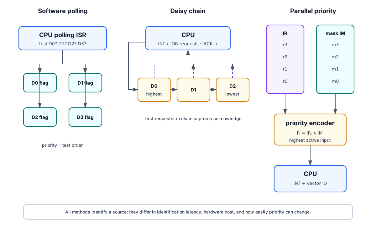
| Method | How source is found | Priority | Trade-off |
|---|---|---|---|
| Software polling | ISR reads device flags in order | Poll order | Little hardware, long/variable latency |
| Daisy chain | Acknowledge propagates until requesting device captures it | Physical chain order | Simple; lower devices wait and chain delay grows |
| Parallel priority | Masked requests feed priority encoder | Hardware-defined/programmed | Fast and flexible; more logic |
A parallel unit commonly uses an interrupt-request register , mask register , and priority encoder:
The encoder selects the highest active and supplies a vector or identification code.
ISR housekeeping
Entry may mask lower-priority sources, clear interrupt status as required, save processor registers, then re-enable higher-priority interrupts. The source-specific service follows. A safe exit sequence is:
- Clear global interrupt enable
IEN. - Restore processor registers.
- Clear the serviced source’s request bit.
- Restore lower-priority mask bits.
- Restore the return PC and set
IEN.
Interrupts must not be accepted during the critical restore interval; otherwise the return address or saved state can become ambiguous. Hardware stacking can reduce this latency, but it does not remove the logical requirements.
Direct Memory Access
DMA removes the CPU from the per-word data path. A DMA controller becomes bus master and transfers directly between a peripheral and memory.
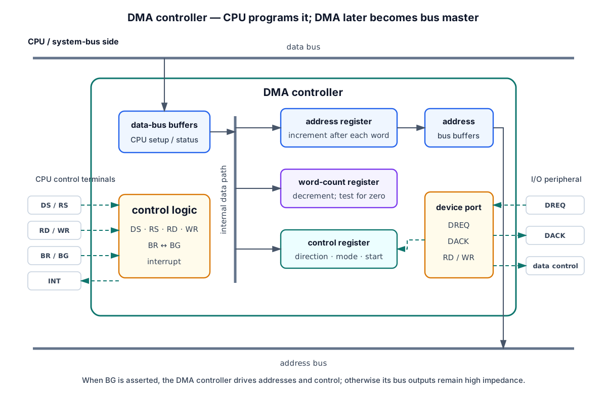
Controller registers and signals
| Item | Function |
|---|---|
| Address register | Current memory address; incremented after each word |
| Word-count register | Words remaining; decremented and zero-tested |
| Control register | Direction, mode, start, channel options |
DS, RS | DMA and internal-register selection during CPU setup |
BR, BG | Bus request from DMA and bus grant from CPU |
DREQ, DACK | Peripheral request and DMA acknowledgement |
RD, WR | CPU inputs during setup; DMA outputs when bus master |
| Interrupt | Reports block completion or error |
The CPU initializes four items: starting memory address, word count, read/write mode, and start control. After that, it need not communicate again until completion, error, or an optional progress check.
DMA Transfer Sequence
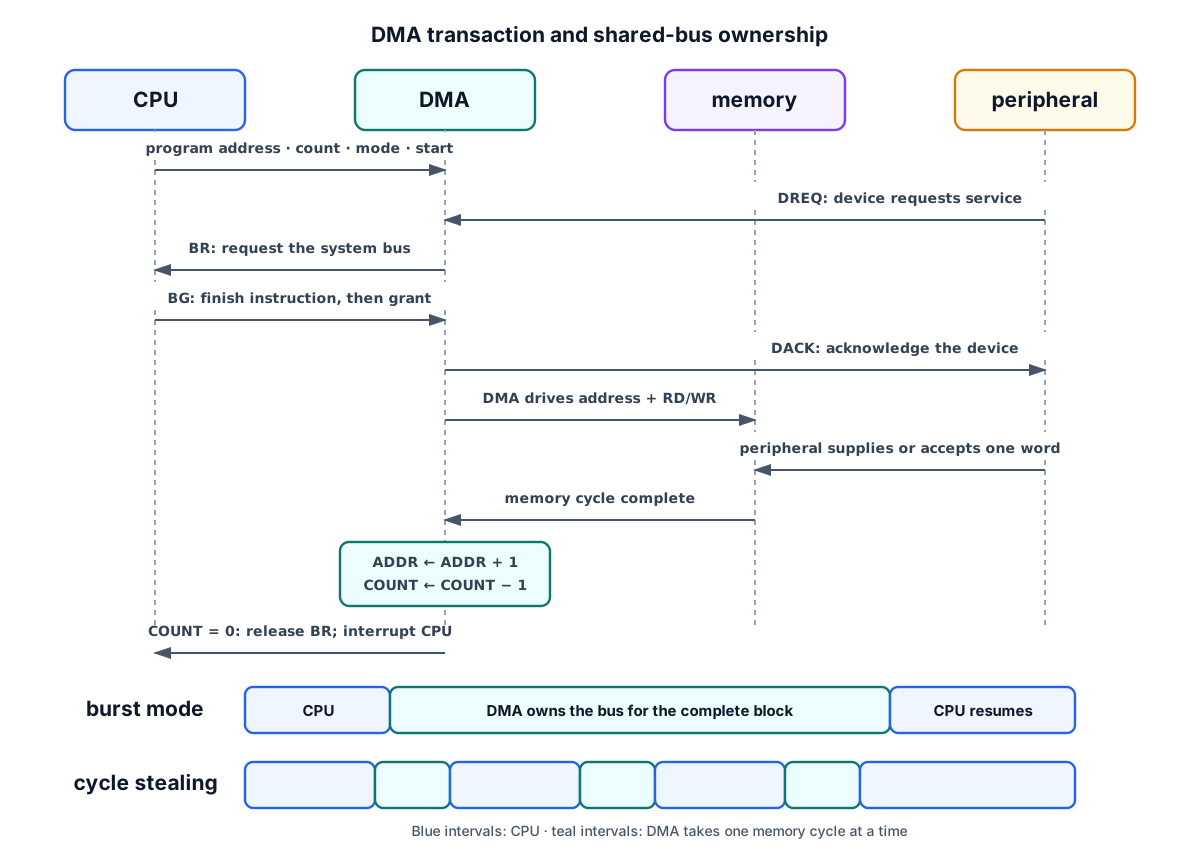
- Peripheral asserts
DREQ. - DMA asserts bus request
BR. - CPU completes its current instruction, places address/data/read/write outputs in high impedance, and asserts
BG. - DMA drives its address register onto the address bus, asserts memory
RDorWR, and acknowledges the peripheral withDACK. - The device supplies or receives the data word.
- DMA increments address, decrements word count, and tests zero.
- If words remain, repeat according to the selected mode. At zero, remove
BRand interrupt the CPU.
Suppose a 1024-word input block begins at 0x8000. CPU initializes ADDR=0x8000, COUNT=1024, direction device-to-memory. After 300 successful words, ADDR=0x812C and COUNT=724 (assuming word-address increments of one). At completion, ADDR=0x8400, COUNT=0, and memory locations 0x8000–0x83FF hold the block.
Burst and cycle stealing
- Burst: DMA holds the bus for the complete block. Throughput is high, but the CPU cannot use the bus during the burst.
- Cycle stealing: DMA transfers one word, releases the bus, and requests again later. CPU progress is slowed by individual stolen memory cycles rather than stopped for a whole block.
- Transparent/background DMA: transfer only when the CPU is not using the bus, reducing interference at the cost of variable device throughput.
A multi-channel DMA controller gives each channel request/acknowledge signals and usually separate address/count state. Internal priority selects a channel when requests coincide.
I/O Processor
An I/O processor (IOP) is a processor specialized for I/O with direct-memory access. Unlike a DMA controller, which the CPU configures completely for a fixed transfer, an IOP fetches and executes its own I/O instructions. It can branch, perform arithmetic/logic, translate codes, manage protocols, and coordinate several devices.
The CPU initiates an I/O program and the IOP proceeds independently, sharing central memory with the CPU. This divides responsibilities:
- CPU executes computational programs.
- IOP performs I/O housekeeping and data movement.
- Memory is the common exchange area.
A communication processor is an IOP specialized for serial links and remote terminals.
Check Your Understanding
- What failure can a handshake detect that a one-way strobe cannot?
- Why are
RDandWRdescribed as bidirectional at a DMA controller? - After 37 transfers from starting address
0x1200, what are address and count if the initial count was 100? - Which priority method encodes priority in cable order?
- What capability separates an IOP from an ordinary DMA controller?
Answers
- Failure or excessive delay of the receiver to accept the data.
- They are inputs while the CPU accesses DMA registers and outputs while DMA controls memory.
ADDR=0x1225,COUNT=63for word-addressed memory.- Daisy chaining.
- The IOP fetches and executes its own I/O program.